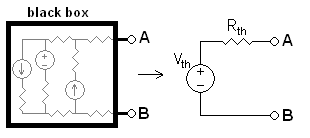
Week Eleven: Thevenin's Theorem Part II

Thevenin's Theorem


Case 2: Independent and Dependent Sources.

          -If the circuit to be Thevenized has both dependent and independent source, the method described above cannot be used to find the Thevenin resistance. Instead, you must find the short circuit current, Isc (current through short circuit at terminals). Then the Thevenin resistance is given by RT=Voc/Isc.
                   
                       
         Example of Circuit Problem using Case 2


Another Case: Only Dependent Sources.
     -If only dependent sources are present, then the Thevenin voltage is zero, and the Thevenin resistance is determine by applying a test voltage Vtest and the terminals and determining the resulting current, Itest. The Thevenin resistance is given by RT=Vtest/Itest. (Likewise, for this third case, you can apply a test current and measure the resulting voltage).
         
 Example of Circuit Problem with Dependent Sources Only


Watch an Example using Thevenin's Theorem Case 2:


Reflection:
       Comparing Case 1 and Case 2, I find case 1 more easy than case 2. Since case 1 only involves Independent sources while case 2 involves Independent and dependent sources.


Week Ten: Thevenin's Theorem Part I

Thevenin's Theorem

     - states that it is possible to simplify any linear circuit, no matter how complex, to an equivalent circuit with just a single voltage source and series resistance connected to a load.
     
     -The theorem was independently derived in 1853 by the German scientist Hermann von Helmholtz and in 1883 by Léon Charles Thévenin (1857–1926), an electrical engineer with France's national Postes et Télégraphes telecommunications organization.

                                                 
                       Hermann von Helmholtz
                                      
                       Léon Charles Thévenin
                       
                        Thevenin Equivalent Circuit:
                                                            

Case 1: Only Independent Sources 
            -the typical case. In the typical case, there are no dependent sources in the circuit to be Thevenized. To find the Thevenin equivalent, first find the open circuit voltage, Voc, this is the Thevenin voltage. To find the Thevenin resistance, set all sources to zero and find the resistance of the resulting circuit.


Consider again the circuit from above,


and try to find the Thevenin circuit at the terminals (i.e., across the 1k resistor). From the discussion of superposition, we know the open circuit voltage, Voc, is 1.666 volts. The Thevenin resistance, RT, is found by finding the equivalent resistance of the circuit with all source set to zero, as shown below


Obviously the Thevenin resistance, RT, is 1k||500=333Ω. Therefore the resulting circuit is:


  Watch Another Example using Thevenin's Theorem!


Reflection:

      I have learned that Thevenin's Theorem makes a complex circuit problem into a simpler one. According to our Professor, it is commonly used especially in Board Examinations for ECE/EE.

Week Nine: Linearity and Superposition

Linearity 

     -is the property of an element describing a linear relationship between cause and effect.

  • The property is a combination of homogeneity(scaling) property and the additivity property.
The homogeneity property requires that if the input (also called the excitation) is multiplied by a constant, then the output (also called the response) is multiplied by the same constant
                          if v = iR ⇒ kv = kiR

The additivity property requires that the response to a sum of inputs is the sum of the responses to each input applied separately
     v1 = i1R, v2 = i2R ⇒ v = (i1 + i2)R = v1 + v2
  • We say that a resistor is a linear element because the voltage-current relationship satisfies both the homogeneity and the additivity properties.

  • A linear circuit is one whose output is linearly related (or directly proportional) to its input.
Superposition
        -The superposition principle states that the voltage across (or current through) an element in a linear circuit is the algebraic sum of the voltages across (or currents through) that element due to each independent source acting alone.


To apply the superposition principle, we must keep two things in mind:

1. We consider one independent source at a time while all other independent sources are turned off. This implies that we replace every voltage source by 0 V (or a short circuit), and every current source by 0 A (or an open circuit). This way we obtain a simpler and more manageable circuit

2. Dependent sources are left intact because they are controlled by circuit variables.

Steps to Apply Superposition Principle:

1. Turn off all independent sources except one source. Find the output (voltage or current) due to that active source using nodal or mesh analysis

2. Repeat step 1 for each of the other independent sources

3. Find the total contribution by adding algebraically all the contributions due to the independent sources.


Watch a Video using Superposition principle!
       

Reflection:
     
      The advantage of superposition is that the circuit can be analyzed with one power source at a time. This will simplify the circuit making the analysis easier. The disadvantage is there is a chance for making an algebraic mistake if we do not keep the same current reference direction each time.

Week Eight : Source Transformation

What is Source Transformation?

         - is simplifying a circuit solution, especially with mixed sources, by transforming a voltage into a current source, and transforming a current into a voltage source.


              Fig.2 Symbols of Different Sources

Watch a Video on How to Convert Sources from Voltage to Current and Vice Versa! 


Reflection:
      By using the method of source transformation, I find it more convenient to determine the values of unknowns. By converting them, you may add or subtract the sources depending on their polarities.

Week Seven: Techniques in Analyzing Circuit Part II

Mesh Analysis

      -One easier method of solving the above circuit is by using Mesh Current Analysis or Loop Analysis which is also sometimes called Maxwell´s Circulating Currents method. Instead of labelling the branch currents we need to label each “closed loop” with a circulating current.

What is Mesh?
- is a loop that does not enclose other loops.                 
             

What is a Supermesh?
- when two meshes have a(dependent or independent) current source in common
.


Cases to be considered for Mesh Analysis:

Case 1:
       - A current source exists only in a one mesh

Case 2:
       - A current source exists between two meshes

Steps in Using Mesh Analysis:


1. Check if circuit is planar.


2. Identify meshes, mesh currents, and supermeshes.

a) Rearrange the circuit if possible to position current source on a single mesh.

b) Use i-v characteristic equations of ICS to find mesh currents and reduce the number of unknowns.

3. Write KVL at each mesh and supermesh.

4. Solve for mesh currents.

5. Calculate problem unknowns from mesh currents. If you need to calculate the voltage across a current source you may have to write KVL around a mesh containing the current source.

6. For consistency and elimination of errors, always markall mesh currents in clockwise direction and write down KVLs in the same direction.


Comparison of Nodal Analysis and Mesh Analysis:
    - Examination of the circuit can also tell us which of the two methods are best suited for the circuit in hand. We always want to reduce the circuit equations into the smallest number of equations in the smallest number of unknowns. The number  of equations from nodal analysis and mesh analysis are given:

            NNV = Nnode − 1 − NVS
            NMC = Nmesh − NCS


where NV S and NCS are numbers of voltage and current sources, respectively. Thus, always inspect the circuit, find NVS and NCS, and proceed with the method that results in the smallest number of equations to solve.


Note: You need to check to ensure that the circuit is a planar circuit. If it is not one cannot use mesh analysis and should use nodal analysis.


     Watch a Video Using Mesh Analysis!

Reflection:
        We have now finished discussing the two types of techniques in analyzing a circuit. For me, mesh analysis is more easier than nodal analysis. It may also depend on the person which method is convenient for him/her to use.
             

Wall-E