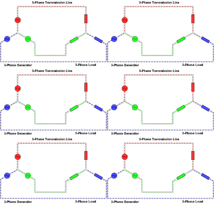
Week Eleven: Three-Phase Circuits

Important Facts:

  • The conductors connected to the three points of a three-phase source or load are called lines.
  • The three components comprising a three-phase source or load are called phases.
  • Line voltage is the voltage measured between any two lines in a three-phase circuit.
  • Phase voltage is the voltage measured across a single component in a three-phase source or load.
  • Line current is the current through any one line between a three-phase source and load.
  • Phase current is the current through any one component comprising a three-phase source or load.
  • In balanced “Y” circuits, line voltage is equal to phase voltage times the square root of 3, while line current is equal to phase current.
  • Three-phase wye “Y” connection has three voltage sources connected to a common point.


Balanced Wye-Wye Connection


Three-Phase Connections Involving Delta Sources or Loads


Watch This Video Now!


Reflection:
    I have learned the different types of three phase connections and how they are produced by generators.

Week Ten: Power Factor and Complex Power


Power Factor


      For a DC circuit the power is P=VI, and this relationship also holds for the instantaneous power in an AC circuit. However, the average power in an AC circuit expressed in terms of the rms voltage and current is


    where is the phase angle between the voltage and current. The additional term is called the power factor
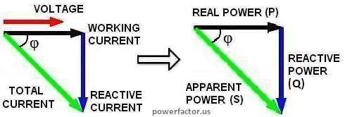
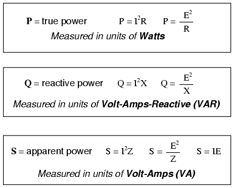
      From the phasor diagram for AC impedance, it can be seen that the power factor is R/Z. For a purely resistive AC circuit, R=Z and the power factor = 1.


Significance of Power Factor

          A power factor of one or "unity power factor" is the goal of any electric utility company since if the power factor is less than one, they have to supply more current to the user for a given amount of power use. In so doing, they incur more line losses. They also must have larger capacity equipment in place than would be otherwise necessary. As a result, an industrial facility will be charged a penalty if its power factor is much different from 1.


Apparent Power
        -is the combination of reactive power and true power. It is the product of a circuit's voltage and current, without reference to phase angle. It is measured in the unit of Volt-Amps (VA) and is symbolized by the capital letter S.
              

For More Information, Watch This Video!

Reflection:
           I have learned the concept behind the power triangle and it's method for finding the unknowns. I'm also surprised that power factor has a big role especially when we are dealing with electricity consumption.

Week Nine: AC Power Analysis

Important terms and formulas to remember:

Instantaneous Power 
p(t)

     -absorbed by an element is the product of the instantaneous voltage v(t) across the element and the instantaneous current i(t) through it. 

p(t) = v(t) i(t)
v(t) = Vm cos(ωt + θv)
i(t) = Im cos(ωt + θi)


Average Power 
         -is the average of the instantaneous power over one period. 


Maximum Average Power Transfer
          -is the maximum amount of power will be dissipated by a load resistance when that load resistance is equal to the Thevenin/Norton resistance of the network supplying the power. If the load resistance is lower or higher than the Thevenin/Norton resistance of the source network, its dissipated power will be less than maximum.


Watch this video for more information!


Reflection:
      I think we must develop a deeper understanding about the basic theories of AC power analysis. Also, we must be able to familiarize ourselves with the formulas. I have learned that power is a significant and common quantity when you are planning to work in a electric company.

Week Eight: Thevenin's Theorem in AC Circuits

Thevenin Equivalent Circuit

  • Thévenin’s theorem, as stated for sinusoidal AC circuits, is changed only to include the term impedance instead of resistance.
  •  Any two-terminal linear ac network can be replaced with an equivalent circuit consisting of a voltage source and an impedance in series.
  • VTh is the Open circuit voltage between the terminals a-b.
  •  ZTh is the impedance seen from the terminals when the independent sources are set to zero.

Ex.1  Thevenin Equivalent At terminals a-b


Watch a Video using Thevenin's Theorem!


Reflection:
    The process used in AC analysis is the same with DC analysis. 


Week Seven: Source Transformation on AC Ciruits

Source Transformation

  • Transform a voltage source in series with an impedance to a current source in parallel with an impedance for simplification or vice versa.

Ex.1 Practice Problem 10.4: Calculate the current Io

If we transform the current source to a voltage source, we obtain the circuit shown in Fig. (a).
By current division,

Watch Another Example of Source Transformation.


Reflection:
   In AC analysis, we applied the same principles used in  source transformation from DC analysis. 


Week Six: Superposition Theorem on AC Circuits


  • A technique called "Superposition" is used to solve for current flow through, and the voltage drop across, any impedance in a multiple source circuit.
Follow these steps:
  1. Replace all but one of the voltage sources with a "short". Current sources are replaced with an "open". (All sources must have the same frequency.)
  2. Solve for the current or voltage flowing through each impedance.
  3. Select the next source and repeat until all sources have been used.
  4. Add all the currents or voltages for each impedance and label the original circuit.
Problem Example:


Please Watch:This video will provide you a further understanding of Superposition Theorem.


Reflection:
   The method used for using superposition theorem in AC circuits is still the same with DC circuits. The difference is that values may be given in complex or phasor form and sources are sometimes shown in different frequencies which requires you to convert them.


Wall-E