Week Five: Techniques in Analyzing Circuit Part I

Nodal Analysis

         - The aim of nodal analysis is to determine the voltage at the each node relative to the reference node (or ground).

Important terms to remember:

  • Reference node- has a potential of 0V by definition.

        The Reference Node SymbolThe Reference Node Symbol
Nodal Analysis with Voltage Sources:
Case 1:

  • If a voltage source is connected between the reference node and a nonreference node, we simply set the voltage at the nonreference node equal to the voltage of the voltage source.

Case 2:
  • If the voltage source (dependent or independent) is connected between two nonreference nodes, the two nonreference nodes form a generalised node or supernode; we apply both KCL and KVL to determine the node voltages. 


The Steps in Using Nodal Analysis are: 

1. Find the essential nodes. 
2. Define one essential node as the reference node. 
3. Define the node voltages, the essential nodes with respect     to the reference node. Label them. 
4. Apply KCL for each non-reference essential node. 
5. Write an equation for each current or voltage upon which  dependent sources depend, as needed.


Watch Video of a Example using Nodal Analysis!


Reflection:

      According to our professor, there two ways in analyzing a circuit. The first one is nodal analysis. This is where we generate equation using voltages. As soon as we obtain the equations, we are encouraged to use the cramer's rule in finding the respected values of voltages in each node. Based on my experience, I find it easy to use the cramer's rule compared to the elimination method or substitution method when we are looking for the values of three unknowns.



Week Four: Series and Parallel Resistors

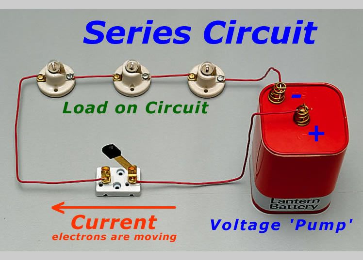
What is a Series Circuit?

                -is a circuit in which resistors are arranged in a chain, so the current has only one path to take. The current is the same through each resistor. The total resistance of the current is found by simply adding up the resistance values of the individual resistors.
                    
Advantages of Series Circuit:
  • Adding Power Devices- you can add the additional power devices, usually using batteries. Doing this will greatly increase the overall force of your output. This will give you more power.
  •  Easy to use- they are easy to learn and to make. It's simple design is easy to understand. this will help you make repairs without the help of a professional.
 Disadvantages of Series Circuit:

  • If one component in a series circuit fails, then all the components in the circuit fails
  • the more components there are in the circuit, the greater the circuit's resistance
What is a Parallel Circuit?


  1. - has two or more paths for current to flow through. Voltage is the same across each component of the parallel circuit. The sum of the currents through each path is equal to the total current that flows from the source.                         
  2.                          
  3.  Advantages of a Parallel Circuit:
  • a failure of one component does not lead to the failure of the other components.
  • more components may be added in parallel without the need for additional voltage.

   Disadvantages of a Parallel Circuit:

  • It requires the use of lot of wires.
  • The source amperage is increased whenever we add a new load to a parallel circuit.
  • Due to proper working sometimes the damage if any, caused to the circuit, may get neglected. This is hazardous.
  • We cannot increase or multiply the voltage in a parallel circuit.
  • Multiple control devices are to be employed for the control of the devices in parallel connection.
  • Parallel connection fails at the time when it is required to pass exactly same amount of current through the units.
  • The design of a parallel circuit is very complex.
  • Additional power sources like batteries cannot be added in parallel connection.
Watch a Video in Solving Series and Parallel Circuits!


Laboratory Activity:
           The experiment was conducted inorder for us to know how to measure the voltage and current in a 7.5 resistor. We plotted the circuit in a breadboard.

Reflection:

          My understanding in series and parallel circuits has increased because my previous learnings are more on basic concepts. I was able to know the formula for current & voltage division and when to use them. I thought that a diagram for representing a series or parallel circuits are always in straight or linear form. Now, I know that they could be represented in a curve way.

Week Three: Basic Laws Part II


Kirchhoff's Law
    -are two equalities that deal with the current and voltage in the lumped element model of electric circuits.

    -first describe in 1845 by Gustav Kirchhoff.


Kirchhoff's Current Law (KCL)
    -The summation of current(I) entering a node is equal to the summation of current(I) leaving the node.

                                                    
Kirchhoff's Voltage Law (KVL)
   -The sum of voltages around a loop is zero(0).
                                   

Important terms to remember:

  • Branch-represents a single element.
  • Nodes-the meeting point between two or more branches.
       Two types of Nodes:     
                1. Reference
                2. Non-reference

  • Loop-any closed loop path in the circuit.


   Watch an Example Problem regarding Kirchhoff's law:


Reflection:


             I was able to learn how to construct an equation using kirchhoff's law with ohm's law. In kirchhoff's voltage law, it doesn't matter whether you use counter-clockwise or clockwise as basis for creating an equation. As long as you are consistent with what you are going to use in order to avoid confusion. 


Wall-E